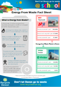
If you and your class have just visited an Energy from Waste plant you probably learnt loads! Why not share it with the rest of your school? The resources on this page will help you plan and deliver a class assembly about energy from waste.
Can you remember the process?
How much rubbish did you see?
What were the best bits about the trip?
How can we use the 3Rs to help reduce the amount of rubbish we produce?
The Powerpoints here will help students and teachers prepare an assembly to talk about your school trip. We’d love to hear from you about how it goes!
EfW – Follow on activity – Powerpoint for EfW Trip to Plymouth
EfW – Follow on activity – Powerpoint for EfW Trip to Exeter
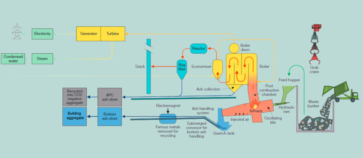
Exeter – How the EfW plant works
Plymouth – How the EfW plant works
Exeter – Energy from Waste process

Tipping Hall
Waste collection lorries deliver the waste to the tipping hall.
Waste Bunker
Waste is stored temporarily in the bunker, where it is mixed until the grab crane moves it to the hopper.
Grabber
The grabber lifts around 1 tonne of waste with each grab – that’s the weight of a baby elephant!
Feed Hopper
Waste is placed into the feed hopper and then pushed into the combustion chamber by a ram.
Combustion Chamber
- The kiln oscillates (moves back and forth) and is tilted to allow the waste to tumble through the cell to ensure that all of it is burnt.
- The kiln has air injected into it to promote combustion and control temperatures of up to 1100°C.
Post Combustion Chamber and Boiler
All gases produced by the combustion process must travel through a post combustion chamber to the boiler. The minimum operating temperature in the post-combustion chamber is 850ºC, in order to burn the waste at a high enough heat to limit the production of dioxins. This requirement is maintained under all start up, operating and shutdown conditions. An oil fired booster burner is used where necessary to maintain this temperature i.e to reach temperature again after it’s been shut down for maintenance.
Boiler
- The boiler converts the heat energy from the combustion gas to high pressure steam energy.
- The steam energy passes through the steam turbine to give an electrical output.
Generation of Heat and Electricity
- Around 4.5MW per hour of electricity is generated, of which around 3.75MW is exported to the national grid at all times.
- There is also the potential for up to 13MW of heat to be exported into the local community. A local district heating system is being investigated, but digging up the surrounding building to put in pipes is currently too expensive.
- Also, if more heat is exported, less electricity will be generated.
Economiser
The economiser reuses the residual heat from the flue gases to pre-heat the hot water before it goes to the boiler.
Emissions Control
- Once the gases have passed through the boiler, they are treated to minimise the level of pollution emitted through the stack.
- Hydrated lime is used to neutralise the acidic gases and activated carbon is used to remove residual metals, dioxins and other pollutants.
- After this, the gases are then passed through 42 bag filters, which take out the last impurities and dust particles before being discharged through the stack.
Stack
- The emissions from the stack is monitored at all times by a temperature sensor, a pressure transmitter, a flow meter, a dust analyser, multi-component gas analyser and a volatile organic compound (VOC) analyser. This data is transmitted to the computer in the Control Room.
- Emissions have to comply with the Industrial Emissions Directive and are set by the Environmental Permit issued by the Environment Agency under which the facility operates. The data is available online for the general public to access at all times.
Bottom Ash
- Ferrous metals are removed using an electromagnet and will be recycled into new products.
- Bottom ash (approximately 20% of the input waste) is sent away to be turned into aggregate and used as a construction material for things such as roads.
Air Pollution Control (APC) Ash
APC Ash (approximately 3% of input waste by weight) is collected by a company that neutralises its hazardous nature and turns the ash into building blocks.
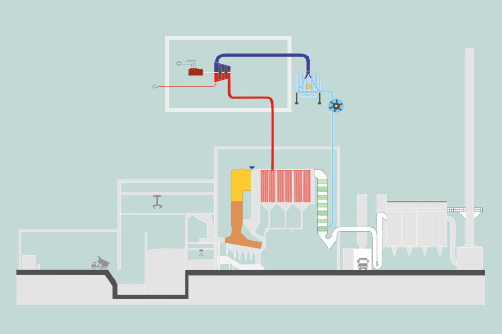
Plymouth – Energy from Waste process

Tipping Hall
- Waste is delivered to the facility in lorries. They enter the enclosed tipping hall and reverse up to the bunker edge. Air is sucked through the tipping hall and bunker and into the furnace so that odours do not escape.
Waste bunker
- The waste is stored in the bunker waiting to be loaded into the furnace by crane.
- Around 10 days worth of waste can be stored here.
- Air is sucked through the tipping hall and bunker and used in the furnace so that odours do not escape.
Furnace
- The waste is burnt under very carefully controlled conditions to ensure safe and complete combustion, and maximise the amount of heat recovered as useful energy.
- The walls of the furnace are made up of pipes within which water is heated and turned into steam in the boiler drum.
Bottom ash
- Those bits of the waste that don’t burn, eg metals and bricks, are part of the ash that falls off the furnace grate. This falls into water to cool it and is then put into a separate bunker before being taken away for recycling.
Boiler
- The very hot gases from the furnace are passed through the boiler.
- The steam from the boiler drum goes through tubes in the boiler to superheat it, ready to be sent to the turbine.
Air Pollution Control (APC) system
- Having given up most of their energy to create useful heat in the form of steam, the flue gases have to be cleaned before they enter the chimney.
- The flue gases are injected with activated carbon and lime which react with pollutants such as acidic gases.
- The filters at the end of the system ensure that the residues, together with dust from the furnace, are captured so that the flue gas entering the chimney is well within the limits set by law. The system is controlled “real time”.
Chimney
- The chimney height will be calculated to ensure that the limited emissions allowed under law are dispersed safely.
Turbine hall
- Superheated steam from the boiler is sent to the turbine where it is used to drive an alternator, generating useful electrical energy.
- Steam can also be taken from the turbine at pressures and temperatures suitable for use by local industry. This reduces their dependency on fossil fuels and improves the overall efficiency of the facility.
Air cooled condenser
- The condenser takes the exhaust steam from the turbine. Very quiet fans send cool air up through the condenser tubes. Warm water goes back to the boiler, where it is used to make steam again.
Energy distribution
- The energy in the waste has finally been turned into useful electricity and steam for use by local industry.
- Any excess electricity is sent to the grid locally, displacing fossil fuels.
- Steam will be sent to local industry through an above ground pipeline.
Site Visits For Schools
Devon Schools can book to visit our waste management facilities in Exeter and Plymouth. The visits are free of charge and link well with topics such as Sustainability, Looking after our World and Recycling. The visits are suitable for Year 4 and above.
Schools in Devon should contact lucy.mottram@devon.gov.uk for more details or see the information on our Site Visits page.


